While I had some free time, I decided to put together the Control Approach rudder pedals that I had purchased and received at the start of the year.
Paul at Control Approach does offer fully assembled pedals for purchase, and I believe that may be the default option when purchasing a set today, but when I ordered in January I decided to save a few bucks and assemble them myself.
I am also using Beringer brakes and wheels, so I had to incorporate attaching the master cylinders to the rudder pedal assembly, along with the correct fittings.
 |
| Prior to assembly - identify and layout all parts needed |
The instructions provided for assembly were quite comprehensive and included several color photos that helped clarify the step-by-step process outlined in the text. I did, however, read through the instructions a few times before beginning assembly to make sure I fully understood each step and identified the correct parts to be used.
The first step in assembly involves attaching the flipper linkage arms to the top of the vertical pedal legs. These arms will also attach to the tops of the four Beringer master cylinders (2 per side).
 |
| Four flipper linkage arms along with parts to attach them to the rudder pedal arms |
 |
| Flipper linkage arm with attachment hardware laid out (from left to right): clevis pin, thin washer, flanged bushing, linkage arm, flanged bushing, thin washer, cotter pin |
 |
| Flipper linkage arms attached to vertical pedal legs, making sure they were oriented correctly |
Next, I attached both pilot and copilot pedal halves together by
- sliding a gray bushing over the inner main tube
- wiping red lithium grease over the parts of the main tube that that nest and attach together
- placing a red sleeve bushing over the inboard end of the main tube
- sliding the outer and inner main tubes together
- aligning the transmission bolt holes in the main tube at the center of the pedal assembly
- carefully threading the transmission bolts in place and securing them with safety wire
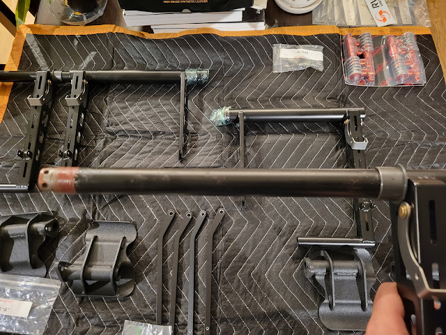 |
| Gray flanged main bushing slid over inner main tube all the way to the vertical arm |
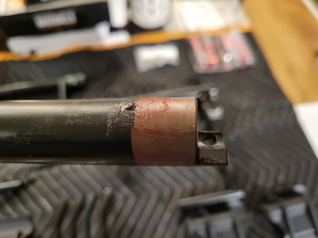 |
| Red lithium grease applied to the inner main tube and connection points |
 |
| Red sleeved bushing place at the end of the inner main tube where the two rudder pedal halves connect |
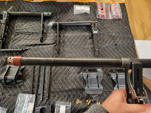 |
| Pilot (left side) rudder pedals showing both bushings in place |
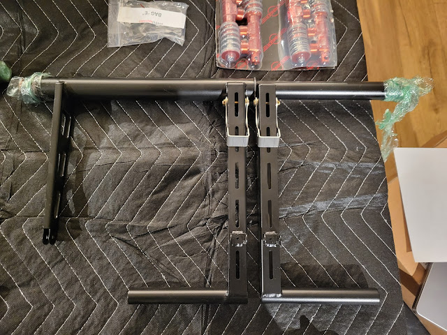 |
| Pilot (left side) outer main tube slid in place with the gray bushing in position between the vertical pedal legs |
 |
| Copilot (right side) main tube aligned with pilot (left side) main tube, and bolt holes aligned |
 |
| Transmission bolts attached with thick washers and torqued to spec |
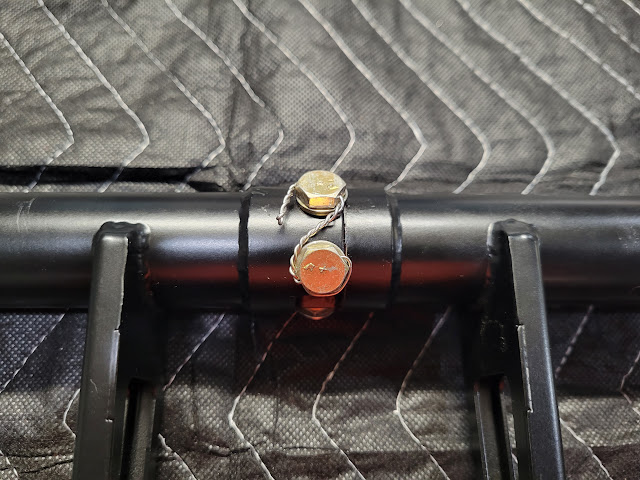 |
| Safety wire added to each pair of bolts for additional security |
With the pedal halves secured together, I was able to work on assembling the brake linkage rods. This involved
- Deburring the stainless steel fork end side plates and reaming the holes to #30
- Attaching a pair of fork end side plates to each brake linkage rod using Cherry-Max rivets (pay attention to the orientation of the plates to the rods when squeezing the rivets to ensure they are as pictured in the instructions)
 |
| Brake linkage rods and fork end side plates |
 |
| Deburring and reaming the fork end side plates |
 |
| I used Knipex pliers to hold the fork end side plates in place while riveting |
 |
Cherry-Max rivets were pulled using my manual rivet puller. While this is not the official tool for squeezing Cherry-Max rivets, it did a good job for the most part (see below)
|
I was able to set the Cherry-Max rivets perfectly on 3 of the 4 brake linkage rods, but on one of them I was not able to squeeze the rivets sufficiently before the mandrel broke off. Drilling the rivets out was a pain, and I ended up slightly enlarging the #30 holes in the side plates and linkage rod. Paul at Control Approach, however, was great in helping me when I reached out to him, and promptly sent out a fully assembled linkage rod to replace the one I had damaged.
Prior to attaching the brake linkage rods to the rudder pedal assembly, I unpacked the Beringer master cylinders and prepared those. Referring to the Beringer installation manual for the RV-10 (which provides some drawings, but not a lot of instruction), I was able to figure out that
- there is a bolt holding down the spring at the top of each cylinder which has to be removed, and replaced with a rod end bearing
- an extension needs to be bolted on to the other end of the master cylinder, and another rod end bearing needs to be threaded into the extension. The extension is required to achieve the recommended 7.5" bearing center to center distance along the length of the master cylinder assembly.
 |
| Bolt removed from the top of each master cylinder allows the spring to expand. A rod end bearing is then threaded in to replace the bolt. The extension seen at the bottom is bolted to the master cylinder, and another rod end bearing is then threaded into the end. Both bearings are secured with jam nuts. |
 |
| All 4 master cylinders ready for attachment to rudder pedal assembly. The rod end bearings were adjusted as needed (by tweaking the threading in or out) to achieve the required 7.5" bearing center to center length. |
Next, I installed the pedals onto the lower pedal bars. This involves
- Inserting Delrin bushings into each side of each pedal tube
- Reaming the hole in each pedal arm to 1/4"
- Pushing a sleeve bushing into each pedal arm hole
- Sliding each pedal onto the lower pedal bars
- Pressing a 3/4" steel push nut onto the pedal bar to hold the pedal in place
 |
| Pedals and bushings that are pushed into each side of the pedal tubes |
 |
| Bushings that are pushed into the pedal arm holes after reaming, along with steel nuts that hold the pedal on the pedal bar |
 |
| Knipex pliers easily took care of squeezing bushings into the pedal arm holes |
 |
| As suggested in Paul's instructions, I used a 3/16" socket to gradually push the steel ring nut on to the pedal bar. That worked really well. A side effect of using these nuts is that they scrape off some of the finish after being pushed on, but there is no way the pedal is coming off without cutting away the nut. I also did make sure to not push the nut too far and interfere with the free rotation of the pedal. |
After getting the brake linkage rods, master cylinders and pedals assemblies done, I was now ready to attach all these to the rudder pedal assembly.
I first tackled attaching the top of the master cylinders and brake linkage rods to the flipper linkage arms.
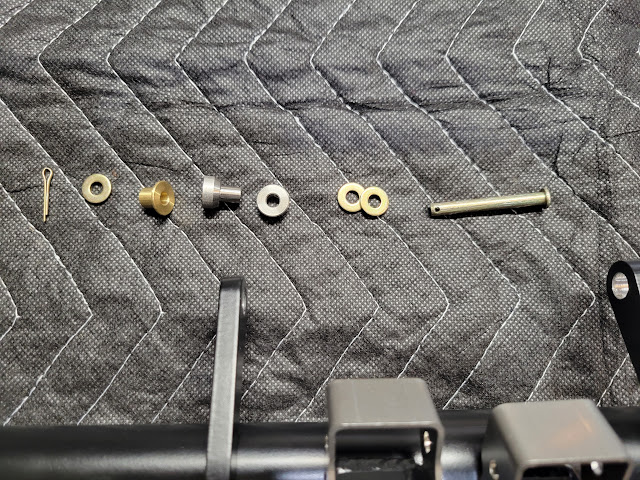 |
| Hardware needed to attach brake linkage rod and Beringer master cylinder to flipper linkage arm (from left to right): cotter pin, washer, flanged bushing, ball end, thick washer, 2 washers, clevis pin. The ball ends and thick washers were provided by Beringer in their RV-10 brake/wheel kit. |
 |
| Two master cylinders and brake linkage rods attached to rudder pedal assembly using the hardware above |
 |
| Make sure to orient the master cylinders so that the hose attachment points face rearward |
The final step in rudder pedal assembly was to attach the bottom end of the master cylinders to the vertical legs, and brake linkage rods to the rudder pedal arms.
 |
| Hardware used to attach brake linkage rods to rudder pedal arms: a clevis pin, washer and cotter pin |
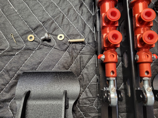 |
| Hardware used to attach master cylinders to vertical legs (from left to right): cotter pin, washer, ball end (again provided in the Beringer kit), washer, clevis pin |
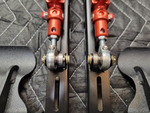 |
| Master cylinders attached! There is about 1/32" of space along the clevis pin to allow for freedom of movement as the brakes are pressed, but the cotter pin prevents anything from coming loose |
 |
| Master cylinders and brake linkage rods fully attached to rudder pedals |
 |
| From the front, the assembly looks really sleek, and the master cylinders (and also eventually the brake hoses) are fully hidden behind the rudder pedals |
 |
| A quick push on the pedals and brakes verified correct operation and movement of the assembly |
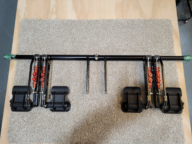 |
| Control Approach rudder pedal assembly rear view |
 |
| Control Approach rudder pedal assembly front view |
Overall, assembly of the rudder pedals was a very streamlined process thanks to the excellent instructions and support that Paul at Control Approach provided. Beringer instructions on the other hand are somewhat more open to interpretation, so I hope my pictures and description above help other builders that may be getting to the point of assembling their own Control Approach/Beringer rudder pedal and brake system.
I can't wait to see how this looks in my RV-10, but now I'm off to work on other build tasks I have been putting off...
Dates: October 23 2024 - October 29 2024
Rudder Pedal Assembly Total Time: 3.4 hours
RV-10 Build Total Time: 850.2 hours
Priming Total Time: 102.2 hours (not included in build time totals)


