Build log documenting construction of my Van's RV-10 airplane.
Started RV-10 on June 29 2022.
Builder #42638
Wing Aileron 21-4-1 to 21-7-6
-
Continuing on section 21 with the ailerons, I pulled out the top and bottom skins and deburred all edges. I then also deburred the stainless steel counterweight tube ends (these were already cut to the length specified in the plans when I received the kit), as well as the aileron spars and nose skin edges.
Aileron parts ready to be worked on again
Several holes need to be drilled into the stainless steel counterbalance tubes, starting with holes that attach the counterbalance to the FL-1004 nose ribs. Rather than drilling through the holes in the aileron skins as suggested in the plans, I chose instead to mark the hole locations in turn on a piece of masking tape attached to the steel tube and then use the drill press to drill the holes. The reason for this was that, having never drilled holes into stainless steel before, I did not want to run the risk of enlarging the holes in the aileron skin. I had read that stainless steel was much harder to drill into than aluminum and there was a possibility of the drill bit wandering when starting to drill.
Fitting the counterbalance tubes into the ailerons
With the counterbalance tube lined up to the edge of the nose rib, I used a sharpie to mark the hole location onto a piece of masking tape that had previously been attached to the tube
Using the drill press to drill holes into the stainless steel
To hold the steel tube securely for drilling with the drill press, I created a simple jig using two pieces of aluminum angle and a long piece of MDF for the base. With everything clamped down, there was no possibility of the steel tube moving or rolling while drilling.
Counterbalance tube securely held in place using my homemade jig
Drilling the steel tube was quite easy using the drill press. I used a brand new #40 cobalt drill bit, drilling fluid and boelube to keep the drill bit cool. The holes ended up exactly where I had marked them, and I was then able to use a #30 drill bit and a #27 spiral reamer to upsize the holes to the required size for the bolts to be used.
Nose rib attach holes drilled and upsized to #27
Nose rib holes also upsized to #27
Next I attached the counterbalance tube to the nose ribs using nuts and steel bolts with a 5/16" wrench to hold the nut, and a cheap offset Philips #2 screwdriver that I purchased on Amazon. This combination worked really well to easily screw in the bolt in the tight spaces of the rib and tube.
Offset screwdriver and wrnech used to attach counterbalance tubes to nose ribs
All holes lined up perfectly and nuts and bolts went in easily
Nose rib permanently attached to the counter balance tube
Ready to move on and drill skin attach holes into the counterbalance tubes
I then reattached the ribs to the aileron spar and clecoed the nose skin in place. Having gotten a feel for drilling into stainless steel, I decided to this time drill the leading edge holes into the tube through the skins.
This actually worked better than I expected, by paying attention to
Keeping the drill bit perpendicular to the skin (using its reflection)
Making sure that the drill bit was held stationary, especially at the start of drilling, to ensure that the drill bit bit into the stainless steel.
Using plenty of cooling fluids so that the drill bit stayed cool while drilling
Pressing firmly into the stainless steel while drilling, and stopping a few times to wipe away chips
Once the hole started forming in the stainless steel, I no longer worried about the drill bit wandering because the hole itself kept everything aligned for the remainder of the drilling.
Skin attach holes being drilled through the skin into the counterbalance tube
To finish off the leading edge holes, I used a #30 spiral reamer which made quick work of enlarging the holes for LP4-3 rivets.
Clecos were used to maintain alignment as the holes were drilled and then upsized
#30 holes drilled through the aileron nose skin and counterbalance tube. I was careful to make sure there was no drifting of the drill bit during initial drilling, and to maintain the bit position perpendicular to the skin (using its reflection)
All #30 holes deburred and lining up nicely along the counterbalance tube
Drilling the steel aileron counterbalance tubes generates some sharp burrs on the inside of the tube which are hard to remove using standard deburring tools. To remove the burrs, I taped a half round file to a 3/8" steel rod. This allowed me to reach in and file them away.
Counterbalance tube with holes deburred on the inside down the length of the tube
Makeshift deburring tool with a file duct taped to a steel rod. Worked well!
Next I dimpled the holes common to the aileron stiffeners, end ribs and skins. Spar holes and trailing edge holes get dimpled later.
Aileron skins dimpled for stiffener and end rib atttachment
All 32 aileron skin stiffeners dimpled
After priming the skins and stiffeners, I was able to begin backriveting the stiffeners and end ribs to the skins, paying special attention to the orientation of each part.
Stiffener and rib rivets taped in place
Each rib and stiffener was riveted in turn starting from the center out towards each edge
For the larger ribs, I used a longer back rivet set to reach the rivet
Note that the forward rib tabs are not riveted at this time and sit slightly proud of the skin. The spar will fit in between the skin and rib tab. For this reason I had previously predimpled the respective skin, rib and spar hole, as dimpling these after riveting the ribs to the skin would have been difficult.
Top skin after riveting the ribs and stiffeners on. Backriveting keeps the skin really flat around the rivets!
All 4 aileron skins with stiffeners and ribs riveted on.
Next I reassembled each aileron by first fitting the spar and nose ribs into the nose skin and then inserting the top and bottom skins in turn, similar to how the flaps were reassembled. Once I had the skins clecoed in, I inserted and clecoed the trailing edge wedge, and made sure all skins were tight with no bowing of the spar and no oil canning.
Left aileron reassembled, ready to final drill the trailing edge
On initial fitting of the skins, I noticed some oil canning due to the end rib flanges interfering and pushing against each other. A quick inspection revealed that the flanges of the shorter end ribs were bent slightly outward (during forming), and to get a good fit and tight skins on the ailerons I had to push the flanges of the ribs back to 90 degrees. This was easily done with the hand seamer.
Right aileron reassembled, and ready to final drill the trailing edge
As indicated in the plans, I used a level to check that the spar was not bowed by holding it span-wise along the nose skin midway between the leading edge and the aft edge.
With the ailerons reassembled, I final drilled the trailing edge holes using my angle guide to ensure I was drilling perpendicular to the aileron chord.
Final drilling the trailing edge wedge using my 83 degree angled guide block
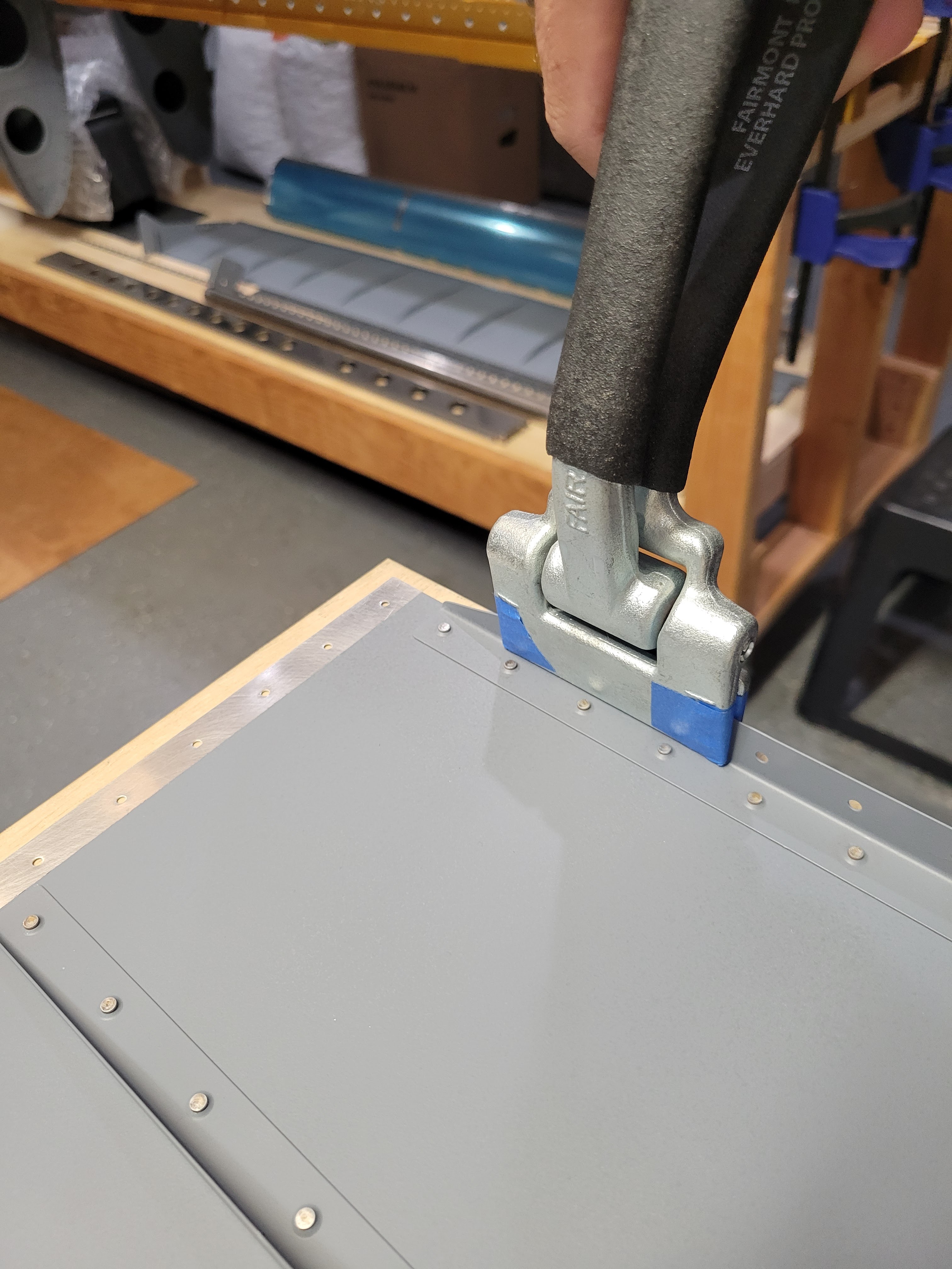
Prior to final assembly, all that remained was to slightly bend the trailing edges of the skins and nose skins for a tighter fit, and dimple the remaining holes for flush rivets.
Using the edge roller to slight crease the trailing edge on the skins. This requires a little more attention here because the stiffeners and end ribs have already been riveted to the skin, but the edge roller fits easily in the space available
Aileron nose skins were both dimpled using the DRDT-2 dimpler, including the nose rib rivet holes
Leading and trailing edges of the aileron skins were dimpled using the pneumatic squeezer. Next to the larger end ribs I had to switch to the narrow female dimple die to avoid damaging the adjacent rib
Holes along the end ribs also need to be dimpled, except for the two forward most holes (which were countersunk previously)
Dimpling of the spar flange holes was accomplished with the pneumatic squeezer after laying down some tape to minimize scratching the spar web
Note that dimpling the spar web causes it to bow slightly as seen above. This bowing will be taken care of during final assembly when the the spar is pulled into line with the nose skin holes.
Build Hints
Deburring the stainless steel counterweight tube ends is easily accomplished using a half round file
Marking holes onto tape placed on the stainless steel tubes, and then drilling those with the drill press worked well to avoid wandering of the drill bit. Be generous with cutting fluid to avoid excessively heating the drill bit and steel. Also be sure to remove the tape immediately after drilling, otherwise the tape adhesive starts to separate due to the cutting fluid and then requires additional cleanup with acetone
If drilling holes into steel using other holes as guides, do not use tape on the steel, just use firm pressure while drilling, and ensure the initial cut starts in the center
A Philips #2 offset screwdriver is recommended for attaching the counterbalance tube to the nose ribs
Keep the following in mind when match drilling through aluminum into stainless steel
Keep the drill bit perpendicular to the skin (using its reflection)
Make sure that the drill bit is held stationary, especially at the start of drilling, to ensure that the drill bit bites into the stainless steel.
Use plenty of cooling fluids so that the drill bit stays cool while drilling
Press firmly into the stainless steel while drilling, and stop a few times to wipe away chips
Make sure the end rib flanges are bent at 90 degrees to the skins otherwise when the skins are inserted into the ailerons, the flanges will meet at an angle and cause oil canning in the skin when the trailing edge is clecoed in place.
When dimpling the end rib flange holes for CS4-4 blind rivets, use 120 degree dimple dies if you have those, and don't dimple the two forward most holes as those were countersunk when the attach brackets were riveted on.
Time Taken: 20.9 hours
Dates: June 7 - June 23, August 29 - October 3 2024
Aileron Total Time: 31.3 hours
RV-10 Build Total Time: 815.1 hours
Priming Total Time: 99.9 hours (not included in build time totals)