Build log documenting construction of my Van's RV-10 airplane.
Started RV-10 on June 29 2022.
Builder #42638
Wing Fuel Tank 18-2-1 to 18-5-2
-
Continuing on with the fuel tanks, I worked on separating the stiffeners. Due to their length, these were easiest to separate using shears. The tabs were then removed on the disc sander. I also cut and kept two vent clips that had been attached to the ends of the pre-formed stiffener angles.
Separating the skin stiffeners using shears
Shears tend to bend the cut edge slightly, especially on the first cut.
I found it better to first cut on the side with the widely spaced notches (where the stiffener end angles will eventually reside), as the bent edge would be trimmed away. The end angles were then marked for cutting with the band saw.
Cuts are made relative to notches in the aluminum angle. I drew lines to help guide a straight cut.
Once the 28 stiffeners were cut to size, final deburring of these and 2 vent clips was done using the deburring wheel. I also reamed all the holes with a #40 reamer.
Stiffeners and vent clips deburred and ready for test fitting to skin
Next I straightened, deburred and fluted the left fuel tank ribs. All #40, #30 and #19 holes were also reamed to remove any burrs within the holes.
Left fuel tank ribs ready for test fitting
I was then ready to start initial assembly of the left fuel tank. The previously deburred skin was put into the leading edge cradles, and the tank stiffeners were clecoed in place along with the fuel drain flange.
Left tank stiffeners clecoed into position
Fuel drain flange holes are already countersunk for rivets
The two inboard bottom stiffeners are slightly too long, and the plans have you match drill an additional hole from the skin into those stiffeners, then trim the stiffener lengths down to the new hole.
Inboard bottom stiffeners with new hole match drilled, and marked for trimming
Inboard bottom tank stiffeners after trimming and deburring
Next I clecoed all the ribs in place. It was tough to get the clecoes started, but I figured out a system that worked for me which was
Cleco the top flange of the middle rib to the skin
Cleco the bottom flanges of each rib either side of the middle rib to the skin
Cleco the top flanges of each rib either side of the middle rib to the skin
this requires some force to align the holes, but because the middle rib is already clecoed to the top skin, it helps the skin conform to the rib shape, and makes it easier to fully cleco the ribs either side
Cleco the bottom flange of the middle rib to the skin
Once the middle 3 ribs are fully clecoed, installing the remaining ribs is relatively straightforward as the skin is already pulled into alignment.
Inboard root fwd rib and remaining tank ribs fully clecoed in left tank skin
Outboard left tank rib
Tank ribs lined up nicely after clecoing
With the ribs installed, I was now able to slide the T-1009 skin stiffener into position, and align the marked centerline with the first hole in the skin (leaving 1/4" from hole center to end of stiffener). As with the outboard leading edges, I used magnets to help keep the stiffener in alignment as I match drilled and clecoed it to the skin.
T-1009 skin stiffener match drilled and clecoed
I was then able to insert (after edge deburring) the T-1005 Tank Attach Bracket and cleco it in place along with the remaining aft inboard root rib.
Tank attach bracket and aft inboard rib clecoed in place
I still have to decide whether I'll prime any of the exterior surfaces of the fuel tank
I also clecoed the Fuel Cap Flange into position paying attention to the bend in the flange so that it was oriented correctly with the bend in the skin (thinner part of the flange facing fwd-aft).
Fuel cap flange clecoed in place...
... and fits nicely when turned to the correct orientation
Next I separated and deburred the tank attach bracket shims, and attached two of them to the left tank attach bracket. There is a nutplate attach hole very close to one edge of each shim. These will be dimpled later along with the other nutplate attach holes (to maintain integrity), and the underlying tank attach bracket will be countersunk.
Separating the tank attach bracket shims
Shims deburred and labelled for test fitting
I then decided to tackle fabrication of the fuel tank vent clips. Two of these were originally cut from the tank stiffener angles earlier, but the plans give no guidance on how these should be fabricated. These will eventually be riveted to the most forward hole in the fuel cap flange, and will hold a plastic grommet that will in turn hold the aluminum fuel vent tube.
To accommodate the plastic grommet, the #40 hole in the fuel vent clip needs to be enlarged to 7/16" (thank you RV-14 plans!). I did this using the drill press and the step drill bit, and the holes came out well. I did have to remake one of the vent clips as the enlarged hole was somewhat close (~1/32") to the clip edge. However, making sure that the clip was clamped firmly, and that the step drill was centered in the #40 hole at the start of drilling, the resulting enlarged holes were nicely centered in the limited area.
Drill press set up for enlarging the vent clip hole
Clecoing the vent clip to the fuel cap flange, I found that I also had to trim the clip on one side due to interference with the fuel cap flange preventing it from sitting flat. This was easily accomplished using the disc sander and deburring wheel, and I made sure that I stayed at least 3/16" (2 x rivet diameter) away from the rivet hole center.
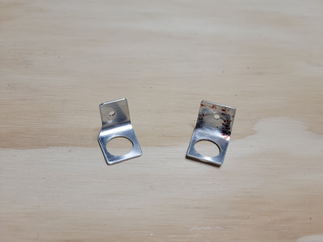
Fuel tank vent clips drilled, and trimmed (on the left) to fit the fuel cap flange
Fuel tank vent clip clecoed to fuel cap flange
Build Hints
Take your time with the initial install of the ribs into the fuel tank. The fit is tight, but installation gets easier as more ribs are inserted and the skin pulls into position. Ensuring that the ribs are properly straightened and fluted makes this process significantly easier.
Fuel cap vent clips need holes enlarged and additional trimming to fit a plastic grommet and attach properly to the fuel cap flange. This is not detailed in the RV-10 plans, but the RV-14 plans contain some helpful instructions.
Time Taken: 12.2 hours
Dates: November 11 - November 21 2023
Wing Fuel Tank Total Time: 15.1 hours
RV-10 Build Total Time: 519.1 hours
Priming Total Time: 50.9 hours (not included in build time totals)


